Research on thermal management of IGBT power modules
Abstract: As insulated gate bipolar transistors (IGBTs) develop toward higher power and higher integration, there have been significant improvements in structure and performance. Heat generation issues have become increasingly prominent, and the requirements for heat dissipation are increasing. IGBT chips are the core functional devices that generate heat, but the accumulation of heat can seriously affect the device's performance. Therefore, effectively monitoring and managing the temperature of IGBT modules is a crucial step. This paper reviews the current research status, research hotspots, and related technologies of IGBT modules, mainly introducing active and passive cooling methods, the main steps in designing thermal resistance network systems and cooling systems for IGBT power modules, and methods to reduce thermal resistance to enhance heat dissipation. The insulated gate bipolar transistor (IGBT) power semiconductor module, as a key component in new energy conversion systems and high-voltage power switching devices, represents a new type of power semiconductor field-controlled self-shutdown electronic device. It is widely used in lighting, automotive, high-speed rail, and other fields. The next ten years will be a golden period for IGBT power module development, with it dominating high-frequency medium to high-power applications. So far, no other product has been found to replace IGBT power semiconductor modules for their key role in power electronic devices. The weakness of IGBT power semiconductor modules is overvoltage and overheating. Therefore, its ability to handle heat limits its high-power applications. IGBTs combine the advantages of metal-oxide-semiconductor field-effect transistors (MOSFETs) and bipolar junction transistors (BJTs), featuring simple drive circuits, low steady-state losses, and strong short-circuit tolerance The parameters and operational performance of power semiconductor modules have also been greatly improved, making them more suitable for power electronic devices. They are the most representative platform devices among high-power semiconductors and can significantly enhance the efficiency of motor drives. As one of the core components of power electronic control circuits, IGBT drives the development of power electronic devices. In recent years, it has grown rapidly and is widely applied in various industries such as metallurgy and renewable energy, helping to leverage sustainable clean energy to alleviate the global fossil energy crisis and environmental issues.
However, as a key component of high-power converters, IGBTs tend to have higher power and higher integration density, and modules generate large amounts of heat due to their high-frequency conduction and opening, affecting device performance. Most IGBT power semiconductor modules fail due to heat. Without effective heat dissipation, module temperatures will quickly reach or even exceed the junction temperature (150 °C), seriously affecting the IGBT's performance, safety, and reliability. This leads to degradation of performance indicators such as switching turnoff speed, on-state voltage drop, current tailing time, turn-off voltage spikes, and losses. Excessively high temperatures can even damage the entire device or even the entire system module, posing a serious threat to the safety and reliability of IGBTs. To meet the growing demands of IGBT device applications, capacity and reliability have become major challenges for IGBT devices. Like other electronic devices, an efficient, stable, convenient, and compact cooling system is crucial for the design of IGBT devices to ensure their safe and stable operation. Thermal management design for IGBT power devices is a necessary and effective measure to address their heat dissipation. This paper provides a comprehensive summary of the current research status, research hotspots, and related technologies for IGBT power module thermal management both domestically and internationally, and provides a thorough organization and analysis. It provides important reference value for solving the challenges of IGBT module thermal design and further lays a theoretical foundation for the reliability design and optimization of device thermal performance.
1 IGBT power device thermal resistance network system
Typically, the downward heat transfer path of IGBT power devices can be described as: when the IGBT power device is energized, the IGBT chip generates a large amount of heat due to on-state losses and switching losses under the influence of voltage and current. The cooling paths from top to bottom are: chip → Ceramic copper-clad laminate → Substrate → The heat sink ultimately transfers heat from the air through convection and radiation, using active or passive heat dissipation to carry away heat. Thermal resistance exists throughout the conduction process, which is the main factor affecting IGBT power module cooling. To enhance cooling performance, reducing thermal resistance is the primary method.
Figure 1 shows the thermal transfer schematic of the IGBT power module in an inverter welding machine. Through soldering, chips, ceramic copper-clad laminates, and substrates are soldered together, and thermal grease is applied between the substrate and heat sink to enhance thermal conduction.
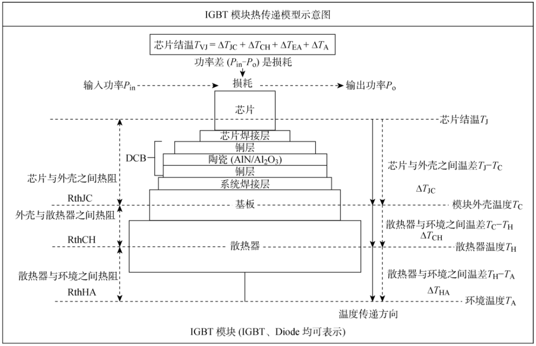
Figure 1: IGBT heat transfer schematic
Structurally, the IGBT power module system in inverter welding machines can be analyzed as the following heat transfer channels: chip Chip soldering layer... Copper. Ceramics→ Copper. System soldering layers. Substrate → Thermal Grease→ Radiators→ Environment. Yin Jiong and others proposed a thermal resistance equivalent circuit method to determine the influence of thermal resistance parameters of the cooling system on system thermal resistance. These parameters include the materials and structural characteristics of power components, the contact between the radiator and module surfaces, etc., and the results determine the degree of impact of different wind speeds on cooling performance and the minimum wind speed to ensure reliable module operation; Deng Erping and others conducted thermal resistance tests using two different methods and conducted comparative studies. The results showed that the traditional thermocouple method is only suitable for measuring the junction-to-shell thermal resistance value of soldered IGBT modules, while the transient dual-interface method is suitable for measuring both the junction-to-shell thermal resistance of soldered IGBT modules and the junction-to-shell thermal resistance of crimp-type IGBT modules.
The thermal resistance network mainly consists of three components: material bulk thermal resistance, thermal interface material thermal resistance, and component-to-environment thermal resistance. Therefore, the total thermal resistance model from the IGBT chip to ambient temperature can be expressed as:
R=Rjc+Rcs+Rsa (1)
Where: Rjc is the thermal resistance from the IGBT chip to the copper substrate; RCS is the thermal resistance from the copper substrate to the heat sink; RSA is the thermal resistance from the radiator to the external environment.
Currently, the internal structure of IGBT power modules is already very mature. It is well known that reducing interfacial thermal resistance and material thermal resistance inside the module is very difficult. Therefore, current heat dissipation focuses on RSA research, aiming to reduce thermal resistance and quickly dissipate the heat generated by the module into the air, lowering the module temperature. This article mainly reviews the thermal dissipation technologies from IGBT modules to the environment, mainly divided into active and passive cooling. Cooling technologies include heat pipe cooling, PCM-based heat sinks, air jets, and liquid jets.
2 IGBT power module heat dissipation analysis and design
As a core component in energy conversion and transmission, IGBTs are widely used in chemical, metallurgy, rail transit, and new energy fields, making significant efforts to alleviate the global fossil energy crisis and environmental issues through sustainable clean energy. Power modules transfer heat to the atmosphere through conduction, convection, and radiation. Depending on the thermal density of IGBTs and application scenarios, different cooling methods are needed, mainly divided into passive cooling and active cooling. The main difference between the two is that passive cooling dissipates heat into the atmosphere through natural convection, without relying on external forces, while active cooling uses air or water cooling, relying on external forces to transfer heat to the air through forced convection. Passive cooling is simpler in structure, less costly, and more reliable than active cooling, but its cooling effect is not very obvious. Active cooling works better by relying on external forces and cools quickly. Thermal analysis and design of IGBT power modules based on thermal resistance network system models may achieve optimal cooling performance.
3. IGBT power module cooling technology
3.1 Passive Heat Dissipation
3.1.1 Fin Cooling Technology
The heat generated by IGBT power modules is naturally convected and dissipated through the radiator fins. According to the Newtonian cooling formula for convective cooling, for a contact surface with area A, the heat dissipation of natural convection cooling is:
Ø =AhΔ t(2)
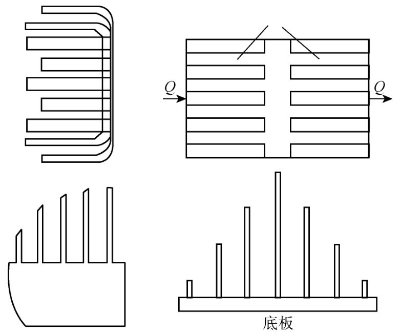
Figure 2: Different arrangements of radiator fins
Common heat sink materials are copper and aluminum alloys, manufactured through die-casting, extrusion, and other processes. Generally, heat sinks are made of aluminum alloy, which not only has good thermal conductivity but also offers high cost performance. Chang et al. developed composite phase-change material straight-wing heat sinks made from paraffin/graphite nanoplates for thermal management of IGBTs. Composite pulse code modulation (PCM) is stored in the cavity of aluminum radiators. GNPs, as an effective thermal medium, enhance PCM activity to improve paraffin thermal conductivity. Differential scanning calorimeters were used to study the thermal properties of melts, setting temperatures, and latent heat, ultimately finding that the thermal conductivity of the composite material increased nearly fivefold.
3.1.2 Heat pipe cooling technology
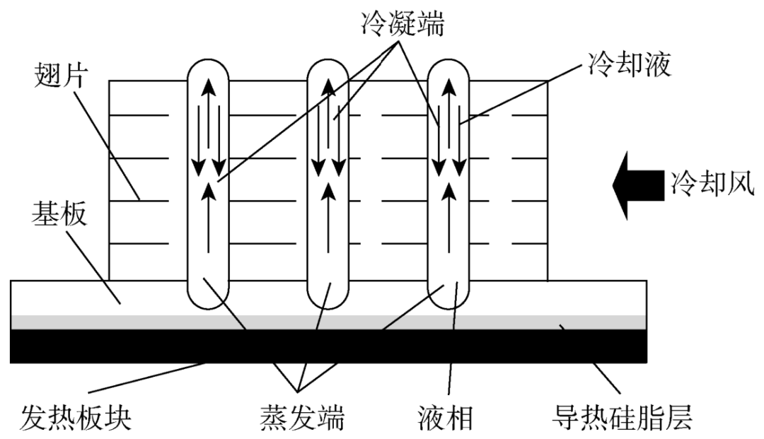
As two-phase heat transfer equipment, heat pipes offer advantages such as low temperature difference, high heat transfer performance, compact size, and excellent temperature consistency. Their mechanisms and working principles are simple, requiring no mechanical maintenance, and offer a very promising solution. Based on the evaporation/condensation cycle, heat pipes have high effective thermal conductivity and the advantage of operating in a purely passive mode. The heat pipe is balanced by a sealed container, core pipe, and a certain amount of working fluid in the liquid/gas state. Heat is applied from the outside to the evaporator and released by the external heat sink of the condenser. Due to the pressure difference between the hot and cold sections, the generated vapor is driven from the evaporator to the condenser. The liquid produced by condensation flows back to the evaporator through the capillary pump generated by the presence of the core suction structure.
Due to their high thermal conductivity and excellent heat dissipation, heat pipes are widely used in the field of IGBT semiconductor power module heat dissipation. IGBT chips transfer heat to the substrate through heat conduction, which then evaporates and condenses the working fluid inside the fully enclosed vacuum tube shell to release heat into the air, achieving heat dissipation. A schematic diagram of the working principle of a heat pipe radiator is shown in Figure 3.
Where: Ø is the heat dissipation amount; A is the heat dissipation area; h is the convective heat transfer coefficient; Δ t is the temperature difference. It can be seen that the heat sink can be enhanced by increasing A and increasing H to enhance cooling performance.
When IGBT power modules undergo natural convective heat dissipation, the forces affecting the fin's heat dissipation flow field are mainly divided into two categories: the driving force of the natural convective flow field and the resistance of the fin array. Figure 2 shows examples of two different fin arrangement forms. Relevant parameters such as fin spacing, structure, height, and orientation all affect the fin's heat dissipation performance. Charles and others constructed fins of various shapes, including trapezoids, inverted trapezoids, rectangles, and more. Experimental results show that the heat transfer coefficient of an inverted trapezoid is 25% and 10% higher than that of a trapezoid and a rectangle, respectively. Design and optimize the finning thickness, height, and spacing of horizontal plate finned radiators, generally aiming to use minimal material and dissipate maximum heat.
Generally, heat pipes are not used as separate heat sinks but are usually embedded with fins for better heat dissipation. Xiahou et al. studied and analyzed the structure of existing IGBT power device heat sinks, and by designing and optimizing array cold-end flat heat pipes, they reduced the size of IGBT power devices and enhanced their cooling performance. Figure 4 is a comparison between traditional heat pipe radiators and array cold-end flat heat pipes.
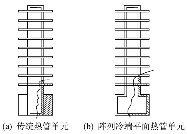
Figure 4: Comparison of two heat pipe units
Figures 4(a) and 4(b) show single tubes in traditional heat pipe radiators and array cold-end flat heat pipes, respectively. In Figure 4(b), the hollow substrate and heat pipe are welded together to form a hollow cavity, with the evaporation end serving as the entire substrate bottom, increasing the thermal contact area of the evaporation end and achieving a uniform temperature effect. By eliminating the thermal resistance of the substrate and the contact thermal resistance between the heat pipe and substrate, the heat transfer performance is improved. Huang et al. proposed a novel symmetrical and highly continuously varying fin array, as shown in Figure 5, which improves natural convective heat transfer by reducing flow resistance.
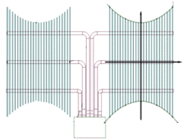
Figure 5 Heat pipe radiator with variable height fin true array
Through three-dimensional numerical calculations, the heat transfer performance of heat pipe radiators with different height-adjustable fin arrays is compared. Research shows that increasing the fin-spacing (s) and maximum fin-height difference (p) can greatly reduce material cost per unit power MTOT, but the impact on total thermal resistance RTOT is more complex. Based on the response surface method, targeting minimum Rtot and Mtot, and integrating the two-stage methods of NSGA-II and TOPSIS, parameter studies and multi-objective optimization analyses were conducted. The resulting Pareto solution set is distributed regionally in the parameter state diagram, indicating that s and p are closely related to system performance rather than independent.
There are many factors that affect heat pipe radiators. Xu Pengcheng and colleagues analyzed heat pipe radiators, established a heat pipe radiator model, and conducted numerical simulations to explore the factors affecting thermal performance: fin thickness and spacing. The results showed that changes in the radiator's friction coefficient and heat transfer factors as fin thickness and spacing varies. Wang Shuangfeng studied the factors affecting the ultimate heat transfer of heat pipe radiators: the length of the condensing section and the pulsating heat pipe heating section. The results showed that to maximize the ultimate delivery capacity, under low liquid filling rates, the length of the heating section must equal the length of the condensing section; At high filling rates, the heating section must be longer than the condensing section.
Over the past decade, many researchers have conducted extensive studies on numerous small prototypes, showing that heat dissipation performance comparable to diamond substrates can be achieved. A vapor chamber is a sealed container similar to a heat pipe, using phase changes to enhance heat dissipation, which has sparked interest in the electronics industry. Some researchers have integrated the vapor chamber between the DBC and the heat sink to replace metal substrates to enhance heat dissipation. Zhang et al. studied integrated power electronics modules, replacing a metal substrate with a vapor chamber (VC) between the DBC and the radiator, eliminating the contact thermal resistance between the module and the radiator. The model is shown in Figure 6. Compared to traditional metal heat sinks, VC greatly diffuses concentrated heat sources over a larger condensation area. Its light weight, good geometric flexibility, and large cooling area greatly enhance the thermal performance of IGBT modules. Chen and others developed a new thermal management system for cooling IGBT power modules. Modules are integrated with vapor-chamber-based radiators to reduce thermal resistance and significantly improve temperature uniformity. The model is shown in Figure 7. Compared with traditional heat sinks, chip junction temperature, internal temperature difference, and maximum thermal stress are all reduced, improving the performance of the IGBT module.
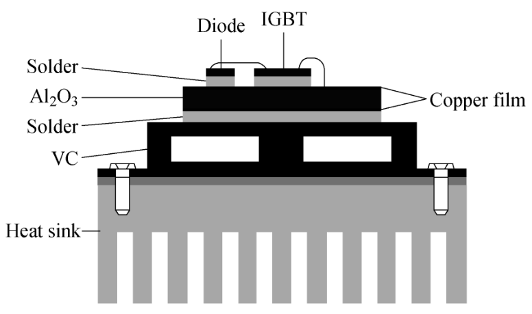
Figure 6 shows the module structure based on VC
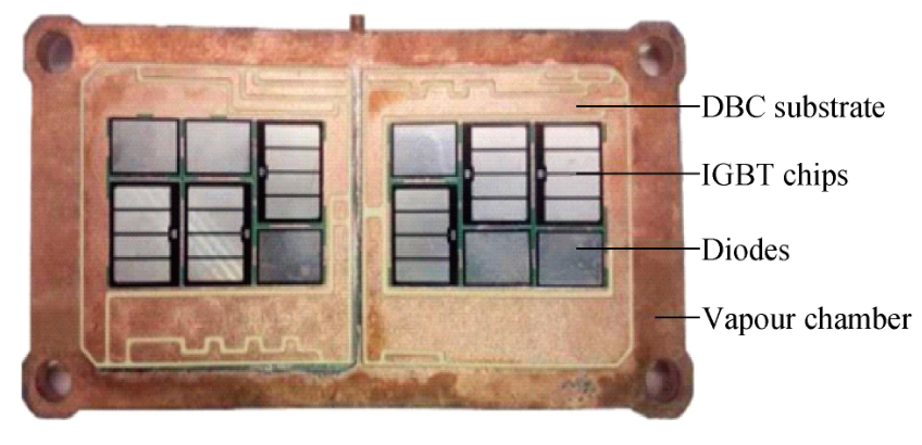
Figure 7 Schematic diagram of the module
Cylindrical heat pipes combined with fins are generally suitable for electronic devices with ample heat dissipation space. The main advantage of flat heat pipes/steam chambers is high temperature uniformity, making them widely used for local heat dissipation. In some small power electronic devices, due to limited heat sources and cooling zones, it is often difficult to effectively utilize traditional cylindrical heat pipes to enhance heat dissipation.
3.1.3 PCM-based heatsinks
As an alternative to thermal management methods such as forced air/liquid convective cooling, PCM cooling is a simple and practical passive thermal management solution that has recently attracted widespread attention in the research community. The advantages of PCM are: higher latent heat of melting provides high energy density, controllable temperature stability, and minimal volume change during phase change. However, PCM has relatively low thermal conductivity. By embedding metal heat sinks, inserting porous metal structures, embedding heat pipes, and mixing highly conductive metal foam and nanoparticles with PCM to enhance thermal conductivity, these are known as thermal conductivity enhancers.
Desai et al. proposed fins to improve the thermal conductivity of PCM modules and conducted numerical studies to find the most efficient heat sink configuration, which limits the critical temperature (Ter) of the thermal control module (TCM), as shown in Figure 8. Important fin parameters to consider in the experiment are the size, quantity, shape, and mass percentage of the fins. The results show that cover plate temperature decreases as the number of fins per quarter geometry increases from 9 to 100, while the increase in fin number enhances local heat diffusion into PCM and leads to a reduction in critical temperature values.
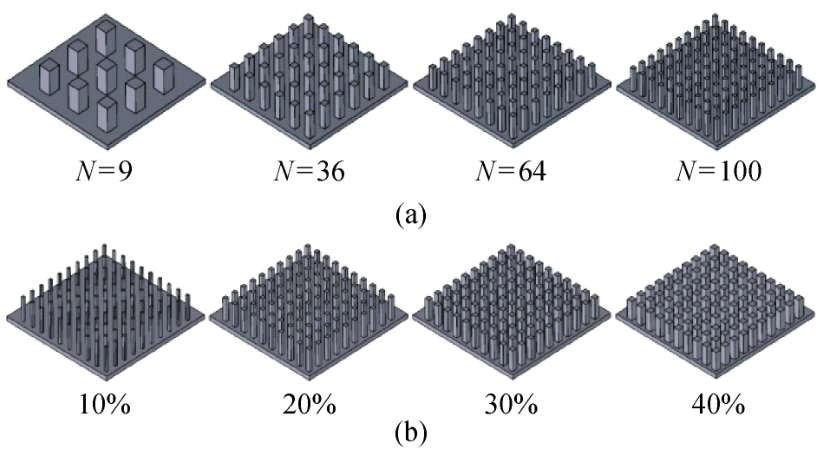
Figure 8 TCM for different fin counts and mass fractions of fins
Experimental studies show that embedding different metal structures in PCM-based heat sinks helps enhance thermal performance. Xie et al. proposed an innovative tree-shaped metal structure embedded in a PCM-based heat sink to better diffuse heat from the concentrated heat source into the PCM housing, as shown in Figure 9. Numerical simulations studied the thermal performance of PCM-based radiators embedded with different types of metal structures under natural convection conditions, specifically including conventional plate fin structures and innovative tree structures obtained through topological optimization. Next, Xie et al. conducted further research on the same innovative tree-shaped metal structure, using two plate-fin radiator structures with 20% and 30% metal volume fractions as benchmarks as benchmarks, and produced optimized tree structures with similar metal volume fractions of 18.7% and 27.6%. A research method based on volume of fluid fluid volume (VOF) and enthalpy-porosity was established to study the dynamic thermal behavior of PCM shells.
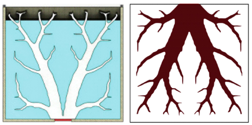
Figure 9 Innovative Tree Metal Structure Diagram
PCM-based heat sinks mainly use the principle of phase change for heat dissipation. In thermal management, PCM can be used for passive cooling or thermal buffering of intermittent electronic components. When PCM melts, it absorbs a large amount of heat, protecting electronic components from overheating. After the modules stop working, the heat absorbed by the PCM module is released into the environment, and the PCM cures to prepare for the next thermal shock.
3.2 Active cooling
Heat sinks are divided into active and passive cooling methods. The process of heat dissipation through thermal convection and thermal radiation between the fins and air is called passive cooling. Passive cooling does not rely on external forces, while active cooling methods add external forces such as fans or liquid cooling to enhance cooling, effectively improving the cooling efficiency by 1~2 energy levels. Dynamic cooling generally comes in two forms: air cooling and liquid cooling technology.
3.2.1 Air cooling cooling technology
As IGBT power devices become more integrated and high-power, heat dissipation issues have become increasingly prominent, and the cooling requirements for IGBT power semiconductor modules are also rising. It is difficult to provide sufficient cooling for high-power and heat-flux IGBT modules with air cooling. Natural convection cooling technology can no longer meet the cooling needs of IGBT power devices, so forced air cooling is needed to accelerate IGBT module cooling and reduce module temperature. Measures to strengthen air cooling heat dissipation mainly include increasing the heat dissipation area, improving the heat exchange coefficient, and reasonably designing air ducts.
Guo Xianmin and others analyzed and studied gaseous cold plates and established a mathematical model under the non-uniform distribution of heat sources on the cold plate surface. As shown in Figure 10, the heat transfer path is: bottom plate & rarr; Cold plate channel → Gas fluids. Zhao Lianquan and others experimentally studied the transient heat transfer characteristics of high-temperature steel plates during air jet cooling. Figure 11 shows that the heat transfer coefficient is affected by temperature changes on the impacted surface during the process, and increasing the gas flow rate can improve heat transfer capacity. Qiu Haiping and others explored the heat dissipation performance of foam aluminum fins in IGBT power semiconductor modules. The results show that, unlike ordinary fin heat sinks, due to their surface area and irregular internal channels, foam aluminum fin heat sinks can enhance heat transfer in IGBT power devices, lower the temperature of power devices, and improve the performance and reliability of power electronic devices.
Compared to natural cooling, forced air cooling can increase heat dissipation by 5~12 times. However, forced air cooling requires the configuration of fans and air circuits, resulting in low reliability and cooling efficiency, and generating significant noise.
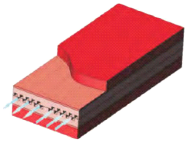
Figure 10 Gas flow inside the cold plate
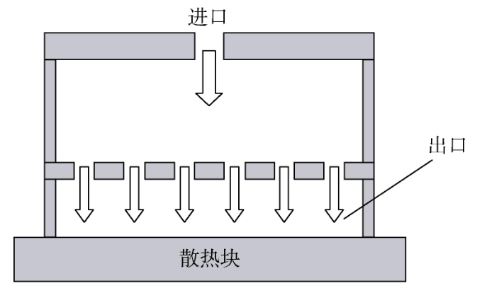
Figure 11 Schematic diagram of the air jet
3.2.2 Liquid Cooling Cooling Technology
When IGBTs operate at high frequencies, thermal loss causes a continuous increase in module temperature rise, which seriously affects the performance of IGBT power semiconductor devices. At the same time, component reliability decreases, greatly shortening component lifespan. More than half of IGBT device failures are caused by thermal failures, making thermal management crucial. Especially when the device has very high power (MWamp level), conditions such as duct design, air pressure supply, and noise indicators make implementation very challenging. Traditional forced air cooling technology can no longer adequately meet device cooling requirements. Water cooling has stronger cooling capabilities and is more suitable for cooling systems of high-power IGBT power semiconductor devices. Currently, water cooling technology is also gradually being widely adopted.
Currently, liquid cooling technology is already very mature. Zhang Cheng and others studied the design of IGBT high-power module water cooling systems. Through simulation and engineering experiments, they solved the parameter design challenges of IGBT cooling systems, ultimately proposing a formula for solving the equivalent thermal resistance of the thermal circuit in water-cooled systems based on similarity theory, and developed methods for designing primary and secondary cooling structure parameters. Jiang Kun and others studied direct water-cooled IGBT power module fin-needle radiators. Through finite element simulation analysis, they summarized the influence patterns of each major parameter on cooling performance, proving the fin-pin diameter, spacing, length, and flow rate when fin-pin radiators achieve optimal cooling performance.
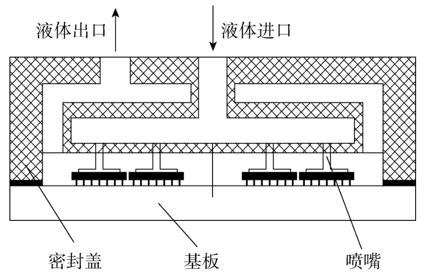
Figure 12 Liquid jet cooling
Direct cooling technology also includes jet cooling for heat dissipation. Navodo explored the jet cooling method, as shown in Figure 12, using jet impact on the surface of the heat-generating module. The results showed that increasing the droplet diameter can enhance the heat transfer coefficient.
Oliphant et al. conducted experiments comparing the heat transfer performance of spray cooling and jet cooling. As shown in Figure 13, spray cooling uses strong pressure to atomize the liquid and spray it onto the surface of the heating block, achieving a cooling effect. The results show that spray cooling has better heat transfer performance.
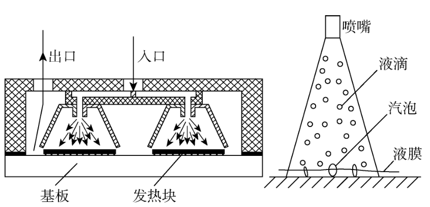
Figure 13 Liquid spray cooling
The power module is in direct contact with the coolant, with no contact thermal resistance, and it also has good temperature uniformity. Research shows that direct liquid cooling can dissipate heat up to 800W/cm².
Generally, depending on whether a copper substrate is included, it can be divided into indirect liquid cooling and direct liquid cooling. Research shows that heat dissipation structures without copper substrates can effectively reduce the overall thermal resistance of the module by 20%~40%, mainly because removing the copper substrate also removes the thermal grease coating. Although the thermal grease coating is very thin, its thermal conductivity is extremely low, which is very detrimental to heat dissipation and causes significant thermal resistance. Therefore, most liquid cooling structures currently used employ direct liquid cooling solutions without copper substrates.
4 Conclusion
IGBT power semiconductor modules are the core components of current power electronic devices, and the accumulation of heat seriously affects device safety, reliability, and performance. Heat dissipation issues are becoming increasingly prominent, and the requirements for module cooling are also rising. To adapt to the development of IGBT power semiconductor components toward higher power and higher integration, based on analysis of IGBT heat dissipation and further improving IGBT cooling performance, existing technologies such as finned cooling, air and liquid cooling, traditional heat pipe cooling, and PCM-based heat sinks are relatively mature. However, considering factors such as heat transfer performance, operational reliability, and system cost, phase change cooling, forced liquid cooling, and micro-cooling technologies have become hot topics in current heat dissipation research. This article focuses on new discoveries related to fins, air cooling, liquid cooling, as well as heat pipes and phase change cooling technologies. Considering all system factors, the technology most suitable for the heat dissipation needs of IGBT power semiconductor components is heat pipe technology that optimizes traditional heat pipe principles and structures. An important future direction is research on heat transfer performance and optimized structure.
Source: Journal of Applied Technology